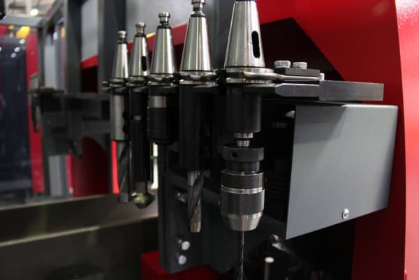
Akyapak 3

Cnc Beam Drill Line Clamp

We always train your operator how to run the machine using Peddimat as you are often going to have the situation where a customer arrives with a couple of pieces of steel that need holes or layout marks and you want to be able to produce them quickly without bothering your detailing staff who might be busy on a larger job.

CNC Drill Line not only processes beams and columns but can also easily process all steel profile including channel, flat, flat, base plates RHS, square and round.

Voortman’ Roller Feed Measurement system exceeds the industry standard for roller measurement technology. Maintaining accurate measurements without any hesitation in production is crucial. Accuracy is not compromised even despite deviations in material.

A 4-axis layout marking attachment eliminates human error in manual layout methods. Part information is retained even after painting, blasting and galvanizing.

Cnc Beam Drill Line Manual

Cnc Beam Drill Line Manual

GSS Machinery will provide you with as many options as you need when drilling with your CNC Drill Line.

Z-Reader Probe- This probe maps the surface's location. It can be operated manually and programmatically. The option is removed from danger and is not active while the cutting process is underway. It can be used for surface mapping or to verify surface at each point before the cutting process begins. It is responsible for initialization, or zeroing the device on the surface at beginning of a program. From there it tracks the difference or accumulates them.
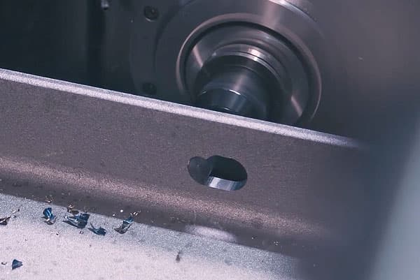
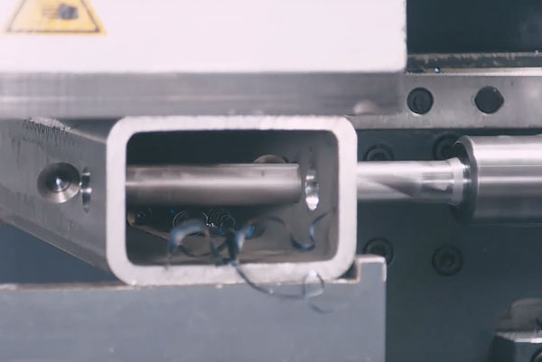
Cnc Beam Drill Line Clamp

Cnc Beam Drill Line Equation

Automatic Edge Finder – The edge finder is or can be utilized manually (Jogging Method & Screen Buttons), programmatically (M & G codes), or fully automatic routine (dedicated program). This option sets offsets & program rotation to match the orientation & location on the cutting table.

The attachment for 4-axis layout marking eliminates human error in manual layout. Even after galvanizing, blasting, and painting, part information can be retained.

Cnc Beam Drill Line Equation

Unit

The CNC Beam Drill Line is a hit among small and medium fabricators, who can fabricate both structural steel as well as miscellaneous metals. The CNC Drill Line was first introduced in 2003 and has been used by more than 600 steel fabricators around the globe.

The Franklin HD145(3) spindle CNC drill is available in 44-inch width. The HD-145 can carry beams upto 750 lbs/foot. Hi-performance spindles provide drilling capabilities of up to 2,000 rpm. This rigid design delivers extremely high feed rates of up 300 surface feet per hour. You can have the Franklin HD145 equipped with various material handling packages, from 300 lbs per ft to 750lbs per ft.

What causes beam failure

Not every problem can be diagnosed with remote assistance. Mechanical issues or questions that require the human eye are still common. Voortman machines are shipped with high definition web cameras and software; allowing Voortman employees to directly experience the activity at the installation without the need to leave the office. The webcam has significant value in foreign countries or in situations where language might be a barrier to effectively communicate the issue.

MultMaster is an extension to the Roller Feed measurement systems. It can perform small-sized cuts that would otherwise need manual positioning. This accessory automates the processing of short residual sections on a Voortman drill-saw tandem system, allowing for quick and easy material processing.

Cnc Beam Drill Line Equation

Check our other pages :

Machinery

GSS Machinery offers a variety of drilling options to drill with your CNC Drill Line.

The FlexBeam is a newly launched machine tool developed for fast, accurate, and economic production of steel profiles. This machine is an efficient beam processing solution for small to medium-sized fab shops, looking to take on larger jobs.

Frequently Asked Questions

The Flange of the L-beam, or the T-beam's slab that acts in unison with the beam to resist loads, is also known as the Flange of the Slab. The beam below the flange can be called Web or Rib. The T-beams support the slab, while the L-beams are the end beams.

The Beam L/D Ratio Diagnostic is used to display a plot of the length/diameter of all the beam elements in the model. The optimal L/D ratio to cool channel-related beam elements is 2.5. Solver convergence warnings may be issued if the L/D ratio is significantly lower.

Section modulus (Z) is another property that can be used in beam design. Designing beams is crucially important because it determines the section modulus of the crosssectional shape. It is an indicator of the strength of the beam.

THE STANDARD SIZE FOR THE BEAMS It is 9" x 12" or 225mm x 300mm in a residential building, according to (IS codes).

Step one is to determine the beam's total load and live load. Identify the type of load that you are supporting (roof, floor, or non-snow) and then choose the span you require. Match the live load and total loads to the values in the tables. You will see the thickness and depth of each required member.